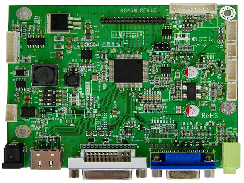
LCD Screen Controller Board
Model:KC46M
Features
◎ Compatible from VGA up to Full HD resolution (1920x1200) TFT LCD panel.
◎ Supply single pixel (24bits) or dual pixel (48bits) digital RGB output.
◎ Support vertical refresh rate up to 75Hz for VGA~1920x1200 and 60Hz for higher resolution of VESA Standard Timing.
◎ Support VGA analog standard input signal 15-pin D-Sub connectors (option).
◎ Automatic detection of separate synchronize and composite synchronizes of VGA.
◎ Support digital signal input DVI 1.0 (option).
◎ Support audio amplifier function (option).
◎ Support High-Definition Multimedia Interface HDMI 1.4 input (option).
◎ RS232 support (option).
◎ IR remote control (option).
◎ DC 12V input.
◎ Operating temperature: -30 °C to +80 °C.
◎ Storage temperature: -40 °C to +80 °C.
◎ RoHS compliant.
This LCD screen controller board is ideal for industrial displays, signage, and embedded systems—offered by a trusted LCD module supplier.
Download
Add to inquiry
◎ Compatible from VGA up to Full HD resolution (1920x1200) TFT LCD panel.
◎ Supply single pixel (24bits) or dual pixel (48bits) digital RGB output.
◎ Support vertical refresh rate up to 75Hz for VGA~1920x1200 and 60Hz for higher resolution of VESA Standard Timing.
◎ Support VGA analog standard input signal 15-pin D-Sub connectors (option).
◎ Automatic detection of separate synchronize and composite synchronizes of VGA.
◎ Support digital signal input DVI 1.0 (option).
◎ Support audio amplifier function (option).
◎ Support High-Definition Multimedia Interface HDMI 1.4 input (option).
◎ RS232 support (option).
◎ IR remote control (option).
◎ DC 12V input.
◎ Operating temperature: -30 °C to +80 °C.
◎ Storage temperature: -40 °C to +80 °C.
◎ RoHS compliant.
This LCD screen controller board is ideal for industrial displays, signage, and embedded systems—offered by a trusted LCD module supplier.
Specification
A/D board option
| Mode | Teleview part no. | Description |
| 1 | C46MA525AIH-- | VGA+DVI+HDMI, audio |
| 2 | C46MA525NIH-- | VGA+DVI+HDMI,No audio |
1. Support Timing Table
| Mode | Resolution | V Freq. (Hz) |
| 1 | 640*480 | 60/75 |
| 2 | 720*400 | 70 |
| 3 | 800*600 | 60/75 |
| 4 | 1024*768 | 60/75 |
| 5 | 1280*720 | 60 |
| 6 | 1280*1024 | 60/75 |
| 7 | 1360*768 | 60 |
| 8 | 1440*900 | 60 |
| 9 | 1680*1050 | 60 |
| 10 | 1920*1080 | 60 |
| 11 | 1920*1200 | 60 |
2. Connector Description
● Connector List
| Connector | Function | Note |
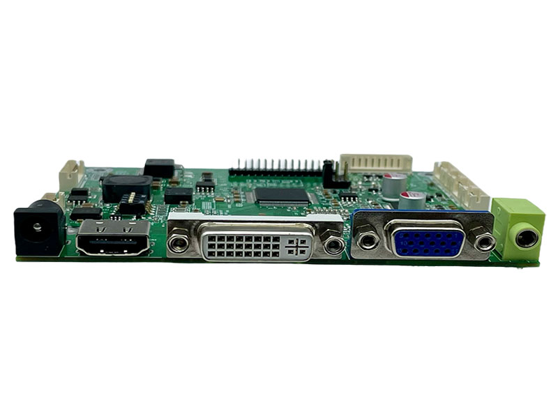
| CN1 | VGA connector | D-15F |
| CN2 | HDMI connector | HDMI A Type |
| CN3 | Audio Line-in Jack | ψ3.5 |
| CN4 | DVI connector | DVI-D(single link) |
| CN5 | Power connector | ψ2.5 |
| J4 | Power connector | PH 2.0mm. 4Pin.180° |
| J5 | LCD Panel for LVDS | PH 2.0mm. 32Pin.180° |
| J6 | Key pad connector | PH 2.0mm. 10Pin.180° |
| J7 | Inverter connector | PH 2.0mm. 8Pin.180° |
| J8 | Speaker connector | PH 2.0mm. 4Pin.180° |
| J9 | UART/ABL Connector | PH 2.0mm. 5Pin.180° |
| J11 | IR Connector | PH 2.0mm. 3Pin.180° |
| J12 | Ext. Amp. connector | PH 2.0mm. 5Pin.180° |
| JP1 | 3.3V/ 5V/ 12V selector | PH 2.5mm. 2x3Pin.180° |
| JP2 | PWM / Analog selector | PH 2.5mm. 3Pin.180° |
| SW1 | Timing selector | PH 2.5mm. 2x4Pin. |
Pin definition for connector
CN1:VGA Connector (15pin D-Sub)
| Pin | Description | Note |
| 1 | VGA R+ | Red analog |
| 2 | VGA G+ | Green analog |
| 3 | VGA B+ | Blue analog |
| 4 | N.C. | Not connect |
| 5 | GND | Analog ground |
| 6 | VGA R- | Analog ground of RED |
| 7 | VGA G- | Analog ground of GREEN |
| 8 | VGA B- | Analog ground of BLUE |
| 9 | VGA 5V | Power of Cable +5Vdc |
| 10 | GND | Analog ground |
| 11 | N.C. | Not connect |
| 12 | DDC SDA | DDC serial data |
| 13 | HSIN | Horizontal synchronous |
| 14 | VSIN | Vertical synchronous |
| 15 | DDC SCL | DDC serial clock |
CN2: HDMI Connector
| Pin | Description | Note |
| 1 | DATA2+ | TMDS Data2+ |
| 2 | GND | Ground |
| 3 | DATA2- | TMDS Data2- |
| 4 | DATA1+ | TMDS Data1+ |
| 5 | GND | Ground |
| 6 | DATA1- | TMDS Data1- |
| 7 | DATA0+ | TMDS Data0+ |
| 8 | GND | Ground |
| 9 | DATA0- | TMDS Data0- |
| 10 | CLK+ | TMDS Clock+ |
| 11 | GND | Ground |
| 12 | CLK- | TMDS Clock- |
| 13 | CEC | CEC |
| 14 | Reserved | Not connect |
| 15 | SCL | I²C serial clock for DDC |
| 16 | SDA | I²C serial data for DDC |
| 17 | DDC/CEC | Ground |
| 18 | +5V | +5 V Power |
| 19 | H-PLUG-DET | Hot Plug Detec |
CN4:DVI-D(single link) Connector
| Pin | Description | Note |
| 1 | DATA2- | TMDS Data 2- |
| 2 | DATA2+ | TMDS Data 2+ |
| 3 | DATA2/4 SHLD | Ground |
| 4 | DATA4- | Not connect |
| 5 | DATA4+ | Not connect |
| 6 | DDC CLK- | DDC clock |
| 7 | DDC DATA | DDC Data |
| 8 | A-VSHNC | Not connect |
| 9 | DATA1- | TMDS Data 1- |
| 10 | DATA1+ | TMDS Data 1+ |
| 11 | DATA1/3 SHLD | Ground |
| 12 | DATA3- | Not connect |
| 13 | DATA3+ | Not connect |
| 14 | +5v | Power for monitor when in standby |
| 15 | DVI DETECT | DVI_CABLE_DETECT |
| 16 | H-PLUG-DET | Hot plug detect |
| 17 | DATA0- | TMDS Data 0- |
| 18 | DATA0+ | TMDS Data 0+ |
| 19 | DATA0/5 SHLD | Ground |
| 20 | DATA5- | Not connect |
| 21 | DATA5+ | Not connect |
| 22 | CLK-SHLD | Ground |
| 23 | CLK+ | TMDS clock+ |
| 24 | CLK- | TMDS clock- |
CN3 : Audio Line-in connector (phone jackψ3.5)

CCN5: Power Connector (2.5ψ3Pin DIP)
| Pin | Description | Note |
| 1 | 12V | Input +12Vdc |
| 2.3 | GND | Ground |
J4: Connector (2.0 mm 4Pin DIP)
| Pin | Description | Note |
| 1,4 | DC 12V | Input +12Vdc |
| 2,3 | GND | Ground |
J5:Panel Connector (2.0 mm 32 Pin DIP)
| Pin | Name ( 8 bit ) | Note |
| 1,2,3,4 | VDD | Power supply for panel |
| 5,6 | GN | Ground |
| 7 | RXEIN3- | EvenTx3- Data Pin |
| 8 | RXEIN3+ | EvenTx3+ Data Pin |
| 9 | RXEINC- | EvenTx- Clock Pin |
| 10 | RXEINC+ | EvenTx+ Clock Pin |
| 11 | RXEIN2- | EvenTx2- Data Pin |
| 12 | RXEIN2+ | EvenTx2+ Data Pin |
| 13 | RXEIN1- | EvenTx1- Data Pin |
| 14 | RXEIN1+ | EvenTx1+ Data Pin |
| 15 | RXEIN0- | EvenTx0- Data Pin |
| 16 | RXEIN0+ | EvenTx0+ Data Pin |
| 17 | RXOIN3- | OddTx3- Data Pin |
| 18 | RXOIN3+ | OddTx3+ Data Pin |
| 19 | RXOINC- | OddTx- Clock Pin |
| 20 | RXOINC+ | OddTx+ Clock Pin |
| 21 | RXOIN2- | OddTx2- Data Pin |
| 22 | RXOIN2+ | OddTx2+ Data Pin |
| 23 | RXOIN1- | OddTx1- Data Pin |
| 24 | RXOIN1+ | OddTx1+ Data Pin |
| 25 | RXOIN0- | OddTx0- Data Pin |
| 26 | RXOIN0+ | OddTx0+ Data Pin |
| 27,28,29,30 | N.C. | Not connect |
| 31,32 | GND | Ground |
J6: Key Board Connector (2.0 mm 10Pin DIP)
| Pin | Function | Note |
| 1 | SEL+(RIGHT) | Increase the value |
| 2 | SEL-(LEFT) | Decrease the value |
| 3 | AUTO | Menu Exit or VGA Auto adjusts |
| 4 | MENU | Enter the main menu |
| 5 | POWER | Power ON/OFF |
| 6 | LED-G | Green LED (Power ON) |
| 7 | LED-R | Red LED (Power saving) |
| 8 | GND | Ground |
| 9 | N.C. | Not connect |
| 10 | N.C. | Not connect |
J7: Inverter Connector (2.0mm 8 Pin DIP)
| Pin | Function | Note |
| 1,2 | 12V Input | Power supply of +12Vdc |
| 4,6 | GND | Ground |
| 3 | Brightness control | 0V – 5V Analog or PWM |
| 5 | ON/OFF Control | 5V ON;0V OFF |
| 7,8 | 5V | +5Vdc |
Note : 2.0mm 5 pin connector(Pin1~5) is used for standard 12V input And stand alone Inverter.
2.0mm 3 pin connector (Pin6~8) is used for 2-in-1 power supply with 5V input.
J8: Audio Speaker Connector (2.0 mm 4Pin DIP)
| Pin | Description | Note |
| 1 | L- | Audio Left- |
| 2 | L+ | Audio Left+ |
| 3 | R- | Audio Right- |
| 4 | R+ | Audio Right+ |
J9: Connector (2.0 mm 5Pin DIP)
| Pin | Description | Note |
| 1 | 5V | Output +5Vdc |
| 2 | ABL | ADC Light Sensor option |
| 3 | Tx | UART TX |
| 4 | Rx | UART RX |
| 5 | GND | Ground |
J11: Connector (2.0 mm 3Pin DIP)
| Pin | Description | Note |
| 1 | 5V | Output +5Vdc |
| 2 | IR | Interrupt input |
| 3 | GND | Ground |
J12: Connector (2.0 mm 5Pin DIP)
| Pin | Description | Note |
| 1 | L_10W | Line out Left |
| 2 | R_10W | Line out Right |
| 3 | Mute_AMP | Control AMP Mute |
| 4 | STB_AMP | Control AMP Power |
| 5 | GND | Ground |
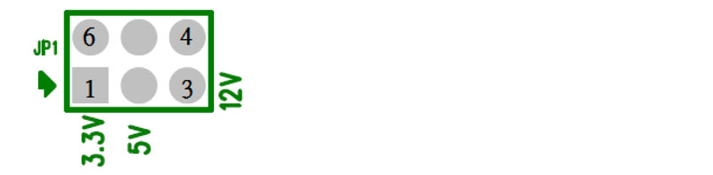
JP1: 5V/3.3V/12V Selector (2.5 mm 2x3 Pin DIP)
| Pin | Description | Note |
| 1-6 | 3.3V | Power supply of +3.3Vdc |
| 2-5 | 5V | Power supply of +5Vdc |
| 3-4 | 12V | Power supply of +12Vdc |
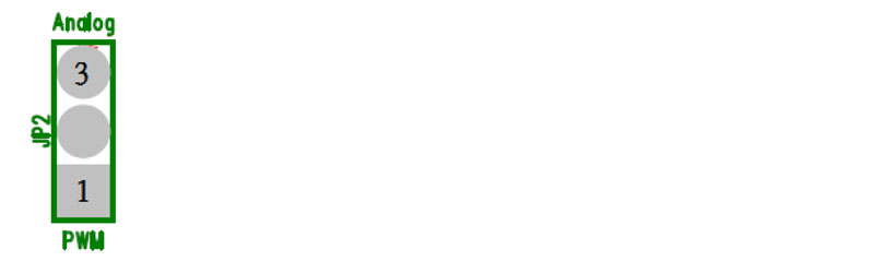
JP2:PWM / Analog selector (2.5 mm 3Pin DIP)
| Pin | Description | Note |
| 1-2 | PWM | Inverter PWM Control |
| 2-3 | Analog | Inverter DC Level Control |
SW1: F/W Timing selector (2.5 mm 2*4Pin SMT)
| Pin | Description | Note |
| 0 | 640*480 | - |
| 1 | 800*600 | - |
| 2 | 1024*768 | - |
| 1,2 | 1280*800 | - |
| 3 | 1280*1024 | - |
| 1,3 | 1366*768 | - |
| 2,3 | 1920*1080 | - |
| 1,2,3 | 1920*1200 | - |
| 4 | 800*480 | - |
| 1,2 | 1024*600 | - |
| 2,4 | 1920*720 | - |
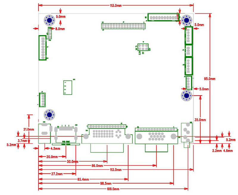
Board Dimension
Board Dimension :113mm*95mm
Screw holes*4:3.5mm
 Download