LCD Module
Model:KC36
This custom LCD module features:
◎ Compatible from VGA up to Full HD resolution(1920x1080) TFT LCD panel.
◎ Supply single pixel(24bits)or dual pixel(48bits) digital RGB output.
◎ Support Vertical refresh rate up to 75Hz for VESA Standard Timing
◎ Support VGA analog standard input signal(15-pin D-Sub connectors).
◎ Automatic detection of separate Sync.Signal and composite Sync.Signal of VGA.
◎ RS232 support (option)
◎ DC 12V input .
◎ Operating temperature : -10 °C to +60 °C .
◎ Storage temperature : -20 °C to +70 °C .
◎ RoHS compliant .
Download
Add to inquiry
◎ Compatible from VGA up to Full HD resolution(1920x1080) TFT LCD panel.
◎ Supply single pixel(24bits)or dual pixel(48bits) digital RGB output.
◎ Support Vertical refresh rate up to 75Hz for VESA Standard Timing
◎ Support VGA analog standard input signal(15-pin D-Sub connectors).
◎ Automatic detection of separate Sync.Signal and composite Sync.Signal of VGA.
◎ RS232 support (option)
◎ DC 12V input .
◎ Operating temperature : -10 °C to +60 °C .
◎ Storage temperature : -20 °C to +70 °C .
◎ RoHS compliant .
Specification
A/D board option
| Mode | Teleview part no. | Description |
| 1 | C36--280ND0-- | VGA, No audio |
1. Support Timing Table
| Mode | Resolution | V Freq.(Hz) |
| 1 | 640*480 | 60/75 |
| 2 | 720*400 | 70 |
| 3 | 800*600 | 60/75 |
| 4 | 1024*768 | 60/75 |
| 5 | 1280*720 | 60 |
| 6 | 1280*1024 | 60/75 |
| 7 | 1360*768 | 60 |
| 8 | 1440*900 | 60 |
| 9 | 1680*1050 | 60 |
| 10 | 1920*1080 | 60 |
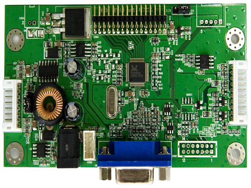
2. Connector Description
● Connector List
| Connector | Function | Note |
| CN1 | VGA connector | D-15F |
| CN2 | Power connector | ψ2.5 |
| CON1 | UART Connector | PH 2.0mm.5Pin.180° |
| CON2 | 12V input Connector | PH 2.0mm.4Pin.180° |
| CON3 | 5V output Connector | PH 2.0mm.2Pin.90° |
| CON4 | Panel connector | PH 2.0 2*16Pin.180° |
| CON5 | Key board connector | PH 2.0mm.10Pin.180° |
| CON6 | Backlight Driver connector |
PH 2.0mm.8Pin.180° |
| JP2 | Analog/PWM selector | PH 2.5mm.3Pin.180° |
| JP1 | 3.3V/5V selector | PH 2.5mm.3Pin.180° |
Pin definition for connector
CON1: UART Connector (2.0 mm 5 Pin DIP)
| Pin | Description | Note |
| 1 | +5V | +5Vdc |
| 2 | Reserved | ADC Light Sensor option |
| 3 | Tx | UART TX |
| 4 | Rx | UART RX |
| 5 | GND | Ground |
CON2: 12V input Connector (2.0 mm 4Pin DIP)
| Pin | Description | Note |
| 1,4 | +12V | Power supply of +12Vdc |
| 2,3 | GND | Ground |
CON3: 5V output Connector (2.0 mm 2Pin DIP)
| Pin | Description | Note |
| 1 | +5V | +5Vdc |
| 2 | GND | Ground |
CON4:Panel Connector (2.0 mm 32 Pin DIP)
| Pin | Name | |
| 1,2,3,4 | VDD | Power supply for panel |
| 5,6,7,8 | GND | Ground |
| 9 | RXEIN3- | EvenTx3- Data Pin |
| 10 | RXEIN3+ | EvenTx3+ Data Pin |
| 11 | RXECLKIN- | EvenTx- Clock Pin |
| 12 | RXECLKIN+ | EvenTx+ Clock Pin |
| 13 | RXEIN2- | EvenTx2- Data Pin |
| 14 | RXEIN2+ | EvenTx2+ Data Pin |
| 15 | RXEIN1- | EvenTx1- Data Pin |
| 16 | RXEIN1+ | EvenTx1+ Data Pin |
| 17 | RXEIN0- | EvenTx0- Data Pin |
| 18 | RXEIN0+ | EvenTx0+ Data Pin |
| 19,20 | GND | Ground |
| 21 | RXOIN3- | OddTx3- Data Pin |
| 22 | RXOIN3+ | OddTx3+ Data Pin |
| 23 | RXOCLKIN- | OddTx- Clock Pin |
| 24 | RXOCLKIN+ | OddTx+ Clock Pin |
| 25 | RXOIN2- | OddTx2- Data Pin |
| 26 | RXOIN2+ | OddTx2+ Data Pin |
| 27 | RXOIN1- | OddTx1- Data Pin |
| 28 | RXOIN1+ | OddTx1+ Data Pin |
| 29 | RXOIN0- | OddTx0- Data Pin |
| 30 | RXOIN0+ | OddTx0+ Data Pin |
| 31,32 | GND | Ground |
CON5:Key Board Connector(2.0 mm 10 Pin DIP)
| Pin | Function | Note |
| 1 | POWER | Power ON/OFF |
| 2 | G-LED | Green LED (Power ON) |
| 3 | R-LED | Red LED (Power saving) |
| 4 | GND | Ground |
| 5 | MENU | Enter the main menu |
| 6 | SEL+( RIGHT) | Increase the value |
| 7 | SEL-( LEFT) | Decrease the value |
| 8 | AUTO/EXIT | Menu Exit or VGA Auto adjusts |
| 9 | N.C. | Not connect |
| 10 | N.C. | Not connect |
CON6: Inverter Connector (2.0 mm 8Pin DIP)
| Pin | Function | Note |
| 1,2 | 12V | Input Power supply of +12Vdc |
| 4,6 | GND | Ground |
| 3 | Brightness control | DC 0V( Max) -5V(Min) or PWM |
| 5 | ON/OFF Control | 5V ON;0V OFF |
| 7,8 | 5V Input/Output | +5Vdc |
Note : 2.0mm 5 pin connector(Pin1~5) is used for standard 12V input And stand alone Inverter.
2.0mm 3 pin connector (Pin6~8) is used for 2-in-1 power supply with 5V input.
JP2: Analog/PWM selector (2.5 mm 3Pin DIP)
| Pin | Description | Note |
| 1-2 | PWM | Inverter PWM Control |
| 2-3 | Analog | Inverter DC Level Control |
JP1: Panel B+ 3.3V / 5V selector (2.5 mm 3Pin DIP)
| Pin | Description | Note |
| 1-2 | 5V | Power supply of +5Vdc |
| 2-3 | 3.3V | Power supply of +3.3Vdc |
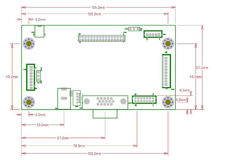
Board Dimension
Board Dimension :105mm*57mm
Screw holes*4:3.5mm
 Download