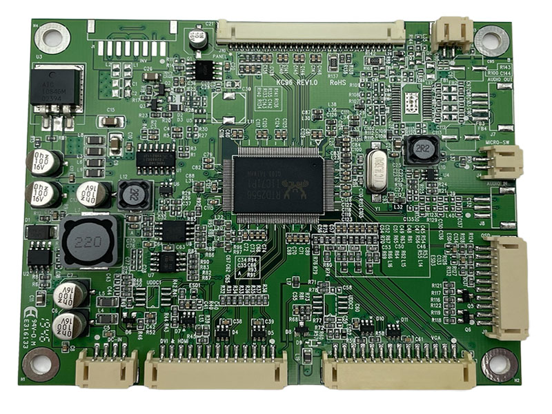
LCD Monitor Circuit Board
Model:KC96
This LCD monitor circuit board offers the following features:
◎ Compatible from VGA up to 1920x1200 resolution TFT LCD panel.
◎ Supply single pixel(24bits)or dual pixel(48bits) digital RGB output.
◎ Support Vertical refresh rate up to 75Hz for VGA~1920x1200 and 60Hz for higher resolution of VESA Standard Timing.
◎ Support VGA analog standard input signal(14-pin 2.0mm connector).
◎ Automatic detection of separate synchronize and composite synchronizes of VGA.
◎ Support Audio Amplifier function with stereophonic output connector (option).
◎ Support Digital Signal input (13 pin 2.0mm connector)
◎ Micro switch detect function for auto-on/off power save . Detect by ground
connection to insure the life of the micro switch .
◎ Full SMD / Slim type (Less than 7.5mm height) specially suitable for KVM .
◎ Support non-linear scaling from 4:3 to 16:9 or 16:9 to 4:3
◎ Support 8-bit output through either eDP
◎ Support 4 lane eDP HBR
◎ Meet RoHS requirement.
Electrical Specification
◎ Power supply
Input for A/D board : 12V DC 3A
Output for eDP Panel : 3.3V / 5V
Output for other board : 5V
◎ Power consumption (Panel / Inverter not included )
Power saving / off : <0.15W / <0.12W
◎ Audio output :
Speaker : 8Ω , 2W
◎ Environment
Operating temperature /humidity : 0℃ ~ 50℃/ 0 ~ 80% ( Non- condensing)
Storage temperature /humidity : -40℃ ~ 70℃/ 0 ~ 90%
Download
Add to inquiry
◎ Compatible from VGA up to 1920x1200 resolution TFT LCD panel.
◎ Supply single pixel(24bits)or dual pixel(48bits) digital RGB output.
◎ Support Vertical refresh rate up to 75Hz for VGA~1920x1200 and 60Hz for higher resolution of VESA Standard Timing.
◎ Support VGA analog standard input signal(14-pin 2.0mm connector).
◎ Automatic detection of separate synchronize and composite synchronizes of VGA.
◎ Support Audio Amplifier function with stereophonic output connector (option).
◎ Support Digital Signal input (13 pin 2.0mm connector)
◎ Micro switch detect function for auto-on/off power save . Detect by ground
connection to insure the life of the micro switch .
◎ Full SMD / Slim type (Less than 7.5mm height) specially suitable for KVM .
◎ Support non-linear scaling from 4:3 to 16:9 or 16:9 to 4:3
◎ Support 8-bit output through either eDP
◎ Support 4 lane eDP HBR
◎ Meet RoHS requirement.
Electrical Specification
◎ Power supply
Input for A/D board : 12V DC 3A
Output for eDP Panel : 3.3V / 5V
Output for other board : 5V
◎ Power consumption (Panel / Inverter not included )
Power saving / off : <0.15W / <0.12W
◎ Audio output :
Speaker : 8Ω , 2W
◎ Environment
Operating temperature /humidity : 0℃ ~ 50℃/ 0 ~ 80% ( Non- condensing)
Storage temperature /humidity : -40℃ ~ 70℃/ 0 ~ 90%
Specification
A/D board option
| Mode | Teleview part no. | Description |
| 1 | C96--556A00-- | VGA+HDMI, audio |
| 2 | C96--556N00-- | VGA+HDMI,No audio |
1. Support Timing Table
| Mode | Resolution | V Freq.(Hz) |
| 1 | 640*480 | 60/75 |
| 2 | 720*400 | 70 |
| 3 | 800*600 | 60/75 |
| 4 | 1024*768 | 60/75 |
| 5 | 1280*720 | 60 |
| 6 | 1280*1024 | 60/75 |
| 7 | 1360*768 | 60 |
| 8 | 1440*900 | 60 |
| 9 | 1680*1050 | 60 |
| 10 | 1920*1080 | 60 |
| 11 | 1920*1200 | 60 |
2. Connector Description
● Connector List
| Connector | Function | Note |
| J6 | VGA input connector | 2.0mm. 14Pin. 90° |
| J5 | HDMI input connector | 2.0mm. 13Pin. 90° |
| J2 | Power input connector | 2.0mm. 4Pin. 90° |
| J10 | LCD Panel for eDP | 1.25mm. 30Pin.90° |
| J9 | Key pad connector | 2.0mm. 10Pin.90° |
| J1 | Inverter connector | 2.0mm .8Pin.90° |
| J7 | Speaker connector | 2.0mm. 4Pin. 90° |
| J8 | Audio line IN | 2.0mm. 3Pin. 90° |
| J4 | Micro SW connector | 2.0mm. 2Pin. 90° |
| J3 | 5V output connector | 2.0mm. 2Pin. 90° |
Pin definition for connector
J1: Inverter Connector (2.0mm 8 Pin SMD)
| Pin | Function | Note |
| 1,2,8 | 12V Input | Power supply of +12Vdc |
| 3,5,7 | GND | Ground |
| 4 | Brightness control | 0V – 5V Analog or PWM |
| 6 | ON/OFF Control | 5V ON;0V OFF |
J9: Key Board Connector (2.0 mm 10Pin SMD)
| Pin | Function | Note |
| 1 | LED-G | Green LED (Power ON) |
| 2 | N.C. | Not connect |
| 3 | LED-R Red | Red LED (Power saving) |
| 4 | N.C. | Not connect |
| 5 | AUTO | Menu Exit or VGA Auto adjusts |
| 6 | MENU | Enter the main menu |
| 7 | SEL+(RIGHT) | Increase the value |
| 8 | SEL-(LEFT) | Decrease the value |
| 9 | GND | Ground |
| 10 | POWER | Power ON/OFF |
J7: Audio speaker connector (2.0 mm 4Pin SMD)
| Pin | Description | Note |
| 1 | R- | Audio Right- |
| 2 | R+ | Audio Right+ |
| 3 | L- | Audio Left- |
| 4 | L+ | Audio Left+ |
J8: Audio line-in connector (2.0 mm 3Pin SMD)
| Pin | Description | Note |
| 1 | GND | Ground |
| 2 | R | Line In Right |
| 3 | L | Line out Left |
J2: Power input connector (2.0mm 4Pin SMD)
| Pin | Description | Note |
| 1,2 | DC 12V | Input +12Vdc |
| 3,4 | GND | Ground |
J3: 5V output (2.0 mm 2Pin SMD)
| Pin | Description | Note |
| 1 | GND | Ground |
| 2 | 5V | +5Vdc |
J4: Micro SW connector (2.0 mm 2Pin SMD)
| Pin | Description | Note |
| 1 | GND | Ground |
| 2 | SW | Switch backlight off |
J6: VGA input connector (2.0 mm 14Pin SMD)
| Pin | Description | Note |
| 1 | RED | Red analog |
| 2 | GND | Ground |
| 3 | GREEN | Green analog |
| 4 | GND | Ground |
| 5 | BLUE | Blue analog |
| 6 | GND | Ground |
| 7 | H. SYNC | Horizontal synchronous |
| 8 | V. SYNC | Vertical synchronous |
| 9 | GND | Ground |
| 10 | DDC SDA | DDC serial data |
| 11 | DDC SCL | DDC serial clock |
| 12 | VGA_5V | Power of Cable +5Vdc |
| 13 | DET_VGA | VGA cable det |
| 14 | NC | Not connect |
J5: Digital input connector (2.0 mm 13Pin SMD)
| Pin | Description | Note |
| 1 | CLK- | TMDS Clock– |
| 2 | CLK+ | TMDS Clock+ |
| 3 | DATA0- | TMDS Data0– |
| 4 | DATA0+ | TMDS Data0+ |
| 5 | DATA1- | TMDS Data1– |
| 6 | DATA1+ | TMDS Data1+ |
| 7 | DATA2- | TMDS Data2– |
| 8 | DATA2+ | TMDS Data2+ |
| 9 | GND | Ground |
| 10 | +5V | Power for monitor when in standby |
| 11 | DDC2 SDA | I²C serial data for DDC |
| 12 | DDC2 SCL | I²C serial clock for DDC |
| 13 | DET | Cable Detect |
J10: Panel connector (1.25 mm 30 Pin SMD)
| Pin | Description | Note |
| 1,2 | NC | No contact |
| 3 | GND | Ground |
| 4 | TXAUXN R | Complement signal Auxiliary Channel |
| 5 | TXAUXP R | True signal Auxiliary Channel |
| 6 | GND | Ground |
| 7 | TX0N R | Complement signal link lane0 |
| 8 | TX0P R | True signal link lane0 |
| 9 | GND | Ground |
| 10 | TX1N R | Complement signal link lane1 |
| 11 | TX1P R | True signal link lane1 |
| 12 | GND | Ground |
| 13 | TX2N R | Complement signal link lane2 |
| 14 | TX2P R | True signal link lane2 |
| 15 | GND | Ground |
| 16 | TX3N R | Complement signal link lane3 |
| 17 | TX3P R | True signal link lane3 |
| 18 | GND | Ground |
| 19,20 | 3.3V or 5V | +3.3V or +5V Power supply |
| 21 | DP_HPD | HPD Signal in |
| 22 | BKLT_EN | Backlight enable |
| 23 | BKLT_ADJ | Backlight Adjustment |
| 24,25 | GND | Ground |
| 26,27,28,29 | 12V | +12V Power supply |
| 30 | NC | No contact |
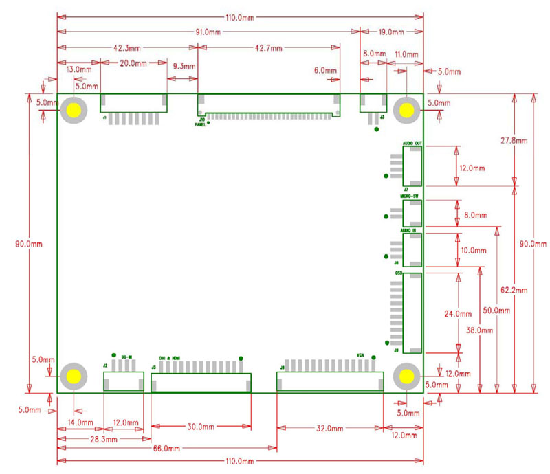
Board Dimension
Board Dimension :110mm*90mm
Screw holes*4:4.3mm
 Download