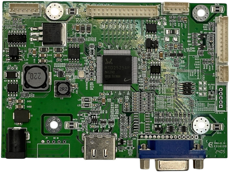
LCD Screen Board
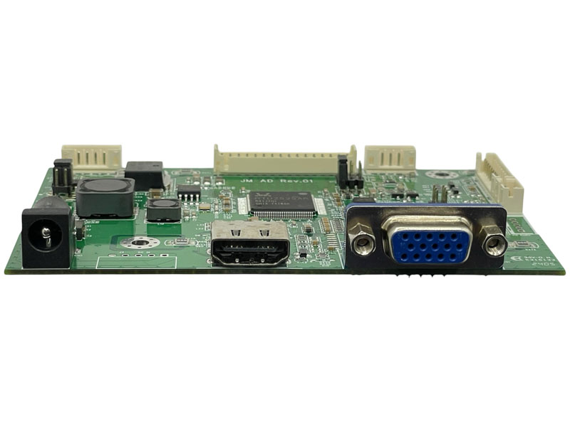
Model:C14
This LCD screen board features:
◎ Compatible from VGA up to 1920x1200 resolution TFT LCD panel.
◎ Supply single pixel(24bits)or dual pixel(48bits) digital RGB output.
◎ Support Vertical refresh rate up to 75Hz for VGA~1920x1200 and 60Hz for higher resolution of VESA Standard Timing.
◎ Support VGA analog standard input signal 15-pin D-Sub connectors (option).
◎ Automatic detection of separate synchronize and composite synchronizes of VGA.
◎ Support High-Definition Multimedia Interface HDMI input (option).
◎ DC 12V input.
◎ Operating temperature : -30 °C to +80 °C.
◎ Storage temperature : -40 °C to +80 °C.
◎ RoHS compliant.
Download
Add to inquiry
◎ Compatible from VGA up to 1920x1200 resolution TFT LCD panel.
◎ Supply single pixel(24bits)or dual pixel(48bits) digital RGB output.
◎ Support Vertical refresh rate up to 75Hz for VGA~1920x1200 and 60Hz for higher resolution of VESA Standard Timing.
◎ Support VGA analog standard input signal 15-pin D-Sub connectors (option).
◎ Automatic detection of separate synchronize and composite synchronizes of VGA.
◎ Support High-Definition Multimedia Interface HDMI input (option).
◎ DC 12V input.
◎ Operating temperature : -30 °C to +80 °C.
◎ Storage temperature : -40 °C to +80 °C.
◎ RoHS compliant.
Specification
A/D board option
| Mode | Teleview part no. | Description |
| 1 | C14--525NH0-- | VGA+HDMI, No audio |
| 2 | C14--525NHX-- | HDMI, No audio |
1. Support Timing Table
| Mode | Resolution | V Freq.(Hz) |
| 1 | 640*480 | 60/75 |
| 2 | 720*400 | 70 |
| 3 | 800*600 | 60/75 |
| 4 | 1024*768 | 60/75 |
| 5 | 1280*720 | 60 |
| 6 | 1280*1024 | 60/75 |
| 7 | 1360*768 | 60 |
| 8 | 1440*900 | 60 |
| 9 | 1680*1050 | 60 |
| 10 | 1920*1080 | 60 |
| 11 | 1920*1200 | 60 |
2. Connector Description
● Connector List
| Connector | Function | Note |
| CN1 | VGA connector | D-15F |
| CN2 | HDMI connector | HDMI A Type |
| CN5 | Power connector | ψ2.5 |
| J4 | Power connector | PH 2.5mm. 5Pin.90° |
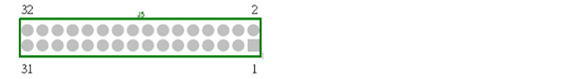
| J5 | LCD Panel for LVDS | PH 2.0mm. 32Pin.180° |
| J6 | Key pad connector | PH 2.0mm. 10Pin.180° |
| J7 | Inverter connector | PH 2.0mm. 6Pin.180° |
| J9 | UART/ABL Connector | PH 2.0mm. 5Pin.180° |
| J11 | IR Connector | PH 2.0mm. 3Pin.180° |
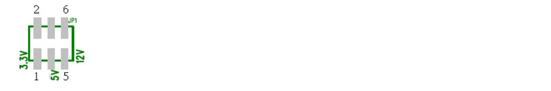
| JP1 | 3.3V/5V/ 12V selector | PH 2.0mm. 2x3Pin.180° |
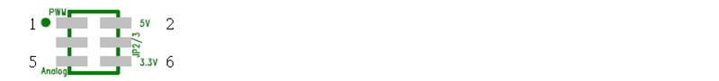
| JP2/3 | PWM / Analog 3.3V or 5V selector |
PH 2.0mm. 2x3Pin.180° |
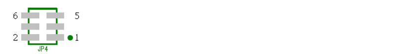
| JP4 | Timing selector | PH 2.0mm. 2x3Pin.180° |
Pin definition for connector
CN1:VGA Connector (15pin D-Sub)
| Pin | Description | Note |
| 1 | VGA R+ | Red analog |
| 2 | VGA G+ | Green analog |
| 3 | VGA B+ | Blue analog |
| 4 | N.C. | Not connect |
| 5 | GND | Analog ground |
| 6 | VGA R- | Analog ground of RED |
| 7 | VGA G- | Analog ground of GREEN |
| 8 | VGA B- | Analog ground of BLUE |
| 9 | VGA 5V | Power of Cable +5Vdc |
| 10 | GND | Analog ground |
| 11 | N.C. | Not connect |
| 12 | DDC SDA | DDC serial data |
| 13 | HSIN | Horizontal synchronous |
| 14 | VSIN | Vertical synchronous |
| 15 | DDC SCL | DDC serial clock |
CN2:HDMI Connector
| Pin | Description | Note |
| 1 | DATA2+ | TMDS Data2+ |
| 2 | GND | TMDS Data2 Shield |
| 3 | DATA2- | TMDS Data2– |
| 4 | DATA1+ | TMDS Data1+ |
| 5 | GND | TMDS Data1 Shield |
| 6 | DATA1- | TMDS Data1– |
| 7 | DATA0+ | TMDS Data0+ |
| 8 | GND | TMDS Data0 Shield |
| 9 | DATA0- | TMDS Data0– |
| 10 | CLK+ | TMDS Clock+ |
| 11 | GND | TMDS Clock Shield |
| 12 | CLK- | TMDS Clock– |
| 13 | CEC | CEC |
| 14 | Reserved | Not connect |
| 15 | SCL | DDC serial clock |
| 16 | SDA | DDC serial data |
| 17 | DDC/CEC Ground | Digital ground |
| 18 | +5V | Power of Cable +5Vdc |
| 19 | H-PLUG-DET | Hot Plug Detect |
CN5: Power Connector (2.5ψ3Pin DIP)
| Pin | Description | Note |
| 1 | 12V | Input +12Vdc |
| 2,3 | GND | Ground |
J4: Power Connector (2.5 mm 5Pin DIP)
| Pin | Description | Note |
| 1 | +12V | Output +12Vdc |
| 2,3 | GND | Ground |
| 4,5 | +5V | Output +5Vdc |
J5:Panel Connector (2.0 mm 32 Pin DIP)
| Pin | Name ( 8 bit ) | Note |
| 1,2,3,4 | VDD | Power supply for panel |
| 5,6 | GND | Ground |
| 7 | RXEIN3- | EvenTx3- Data Pin |
| 8 | RXEIN3+ | EvenTx3+ Data Pin |
| 9 | RXEINC- | EvenTx- Clock Pin |
| 10 | RXEINC+ | EvenTx+ Clock Pin |
| 11 | RXEIN2- | EvenTx2- Data Pin |
| 12 | RXEIN2+ | EvenTx2+ Data Pin |
| 13 | RXEIN1- | EvenTx1- Data Pin |
| 14 | RXEIN1+ | EvenTx1+ Data Pin |
| 15 | RXEIN0- | EvenTx0- Data Pin |
| 16 | RXEIN0+ | EvenTx0+ Data Pin |
| 17 | RXOIN3- | OddTx3- Data Pin |
| 18 | RXOIN3+ | OddTx3+ Data Pin |
| 19 | RXOINC- | OddTx- Clock Pin |
| 20 | RXOINC+ | OddTx+ Clock Pin |
| 21 | RXOIN2- | OddTx2- Data Pin |
| 22 | RXOIN2+ | OddTx2+ Data Pin |
| 23 | RXOIN1- | OddTx1- Data Pin |
| 24 | RXOIN1+ | OddTx1+ Data Pin |
| 25 | RXOIN0- | OddTx0- Data Pin |
| 26 | RXOIN0+ | OddTx0+ Data Pin |
| 27,28,29,30 | N.C. | Not connect |
| 31,32 | GND | Ground |
J6: Key Board Connector (2.0 mm 10Pin DIP
| Pin | Function | Note |
| 1 | SEL+(RIGHT) | Increase the value |
| 2 | SEL-(LEFT) | Decrease the value |
| 3 | AUTO | Menu Exit or VGA Auto adjusts |
| 4 | MENU | Enter the main menu |
| 5 | POWER | Power ON/OFF |
| 6 | LED-G | Green LED (Power ON) |
| 7 | LED-R | Red LED (Power saving) |
| 8 | GND | Ground |
| 9 | N.C. | Not connect |
| 10 | N.C. | Not connect |
J7: Inverter Connector (2.0mm 6 Pin DIP)
| Pin | Function | Note |
| 1,2 | 12V Input | Power supply of +12Vdc |
| 3 | ON/OFF Control | 5V ON;0V OFF |
| 4 | Brightness control | 0V – 5V Analog or PWM |
| 5,6 | GND | Ground |
Note : 2.0mm 6 pin connector(Pin1~6) is used for standard 12V input
And stand alone Inverter.
J9: Connector (2.0 mm 5Pin DIP)
| Pin | Description | Note |
| 1 | +5V | Output +5Vdc |
| 2 | ABL | ADC Light Sensor option |
| 3 | Tx | UART TX |
| 4 | Rx | UART RX |
| 5 | GND | Ground |
J11: Connector (2.0 mm 3Pin DIP)
| Pin | Description | Note |
| 1 | +3.3V | Output +3.3Vdc |
| 2 | IR | Interrupt input |
| 3 | GND | Ground |
JP1: Panel B+ 3.3V /5V / 12V selector (2.0 mm 2*3Pin SMT)
| Pin | Description | Note |
| 1-2 | 3.3V | Power supply of +3.3Vdc |
| 3-4 | 5V | Power supply of +5Vdc |
| 5-6 | 12V | Power supply of +12Vdc |
JP2/3: PWM / Analog & 3.3V/5V Level selector (2.0 mm 2*3Pin SMT)
| Pin | Description | Note |
| 1-3 | PWM | Inverter PWM Control |
| 3-5 | Analog | Inverter DC Level Control |
| 2-4 | 5V | 5V Level Output |
| 4-6 | 3.3V | 3.3V Level Output |
JP4: F/W Timing selector (2.0 mm 2*3Pin SMT)
| Pin | Description | Note |
| 0-0 | AUO G104XVN01.0 | 1024*768 |
| JH104X1-L01 | ||
| BOE DV150X0M-N10 | ||
| 1-2 | BOE MV215FHM-N72 | 1920*1080 |
| BOE MV270FHM-N42 | ||
| 3-4 | 640*480 | |
| 1-2 & 3-4 | 800*600 | |
| 5 - 6 | 1280*800 | |
| 1-2 & 5-6 | 1280*1024 | |
| 3-4 & 5-6 | 1366*768 | |
| 1-2 & 3-4 & 5-6 |
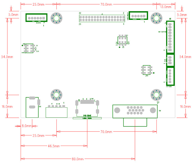
Board Dimension
Board Dimension :108mm x 75mm
Screw holes*4:3.5mm
 Download