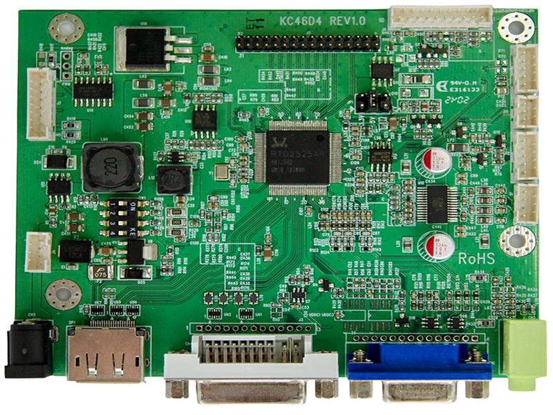
LCD ADボード
モデル:KC46D4
プロフェッショナルLCDモジュール会社として、以下の特徴を持つ信頼性の高いLCD ADボードソリューションを提供します:
◎ VGAからフルHD解像度(1920x1200)TFT LCDパネルまで互換性があります。
◎ シングルピクセル(24ビット)またはデュアルピクセル(48ビット)デジタルRGB出力を供給します。
◎ VGA〜1920x1200まで75Hz、VESAスタンダードタイミングの高解像度では60Hzの垂直リフレッシュレートをサポートします。
◎ VGAアナログ標準入力信号15ピンD-Subコネクタ(オプション)をサポートします。
◎ VGAのセパレートシンクとコンポジットシンクを自動検出します。
◎ デジタル信号入力DVI 1.0(オプション)をサポートします。
◎ デジタル信号入力Display Port 1.2(オプション)をサポートします。
◎ オーディオアンプ機能(オプション)をサポートします。
◎ RS232サポート(オプション)
◎ IRリモコン(オプション)
◎ DC 12V入力。
◎ 動作温度:-30°C~+80°C。
◎ 保管温度:-40°C~+80°C。
◎ RoHS準拠。
ダウンロード
問い合わせに追加
◎ VGAからフルHD解像度(1920x1200)TFT LCDパネルまで互換性があります。
◎ シングルピクセル(24ビット)またはデュアルピクセル(48ビット)デジタルRGB出力を供給します。
◎ VGA〜1920x1200まで75Hz、VESAスタンダードタイミングの高解像度では60Hzの垂直リフレッシュレートをサポートします。
◎ VGAアナログ標準入力信号15ピンD-Subコネクタ(オプション)をサポートします。
◎ VGAのセパレートシンクとコンポジットシンクを自動検出します。
◎ デジタル信号入力DVI 1.0(オプション)をサポートします。
◎ デジタル信号入力Display Port 1.2(オプション)をサポートします。
◎ オーディオアンプ機能(オプション)をサポートします。
◎ RS232サポート(オプション)
◎ IRリモコン(オプション)
◎ DC 12V入力。
◎ 動作温度:-30°C~+80°C。
◎ 保管温度:-40°C~+80°C。
◎ RoHS準拠。
仕様
A/D board option
| Mode | Teleview part no. | Description |
| 1 | C46D4525AIP-- | VGA+DVI+DP,audio |
| 2 | C46D4525NIP-- | VGA+DVI+DP,No audio |
1. Support Timing Table
| Mode | Resolution | V Freq.(Hz) |
| 1 | 640*480 | 60/75 |
| 2 | 720*400 | 70 |
| 3 | 800*600 | 60/75 |
| 4 | 1024*768 | 60/75 |
| 5 | 1280*720 | 60 |
| 6 | 1280*1024 | 60/75 |
| 7 | 1360*768 | 60 |
| 8 | 1440*900 | 60 |
| 9 | 1680*1050 | 60 |
| 10 | 1920*1080 | 60 |
| 11 | 1920*1200 | 60 |
2. Connector Description
● Connector List
| Connector | Function | Note |
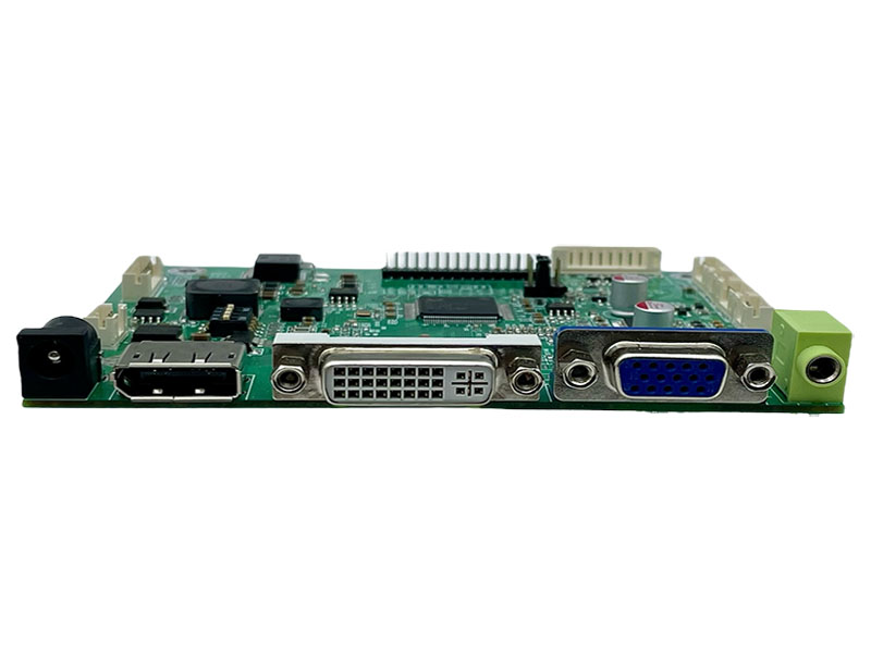
| CN1 | VGA connector | D-15F |
| DP1 | Display Port connector | |
| CN4 | DVI connector | DVI-D(single link) |
| CN3 | Audio Line-in Jack | ψ3.5 |
| CN5 | Power connector | ψ2.5 |
| J4 | Power connector | PH 2.0mm.4Pin.180° |
| J5 | LCD Panel for LVDS | PH 2.0mm.32Pin.180° |
| J6 | Key pad connector | PH 2.0mm.10Pin.180° |
| J7 | Inverter connector | PH 2.0mm.8Pin.180° |
| J8 | Speaker connector | PH 2.0mm.4Pin.180° |
| J9 | UART/ABL Connector | PH 2.0mm. 5Pin.180° |
| J11 | IR Connector | PH 2.0mm. 3Pin.180° |
| J12 | Ext. Amp. connector | PH 2.0mm. 5Pin.180° |
| JP1 | 3.3V/5V/ 12V selector | PH 2.5mm.2x3Pin.180° |
| JP2 | PWM / Analog selector | PH 2.5mm.3Pin.180° |
| SW1 | Timing selector | PH 2.5mm. 2x4Pin. |
Pin definition for connector
CN1:VGA Connector (15pin D-Sub)
| Pin | Description | Note |
| 1 | VGA R+ | Red analog |
| 2 | VGA G+ | Green analog |
| 3 | VGA B+ | Blue analog |
| 4 | N.C. | Not connect |
| 5 | GND | Analog ground |
| 6 | VGA R- | Analog ground of RED |
| 7 | VGA G- | Analog ground of GREEN |
| 8 | VGA B- | Analog ground of BLUE |
| 9 | VGA 5V | Power of Cable +5Vdc |
| 10 | GND | Analog ground |
| 11 | N.C. | Not connect |
| 12 | DDC SDA | DDC serial data |
| 13 | HSIN | Horizontal synchronous |
| 14 | VSIN | Vertical synchronous |
| 15 | DDC SCL | DDC serial clock |
DP1: Display Connector
| Pin | Description | Note |
| 1 | ML_LANE3N | Lane 3 (-) |
| 2 | GND | Ground |
| 3 | ML_LANE3P | Lane 3 (+) |
| 4 | ML_LANE2N | Lane 2 (-) |
| 5 | GND | Ground |
| 6 | ML_LANE2P | Lane 2 (+) |
| 7 | ML_LANE1N | Lane 1 (-) |
| 8 | GND | Ground |
| 9 | ML_LANE1P | Lane 1 (+) |
| 10 | ML_LANE0N | Lane 0 (-) |
| 11 | GND | Ground |
| 12 | ML_LANE0P - | Lane 0 (+) |
| 13 | GND | Ground |
| 14 | GND | Ground |
| 15 | AUX_CHP | Auxiliary channel (+) |
| 16 | GND | Ground |
| 17 | AUX_CHN | Auxiliary channel (-) |
| 18 | HOT_PLUG | Hot plug detect |
| 19 | RETURN | Return for power |
| 20 | DP_PWR | Power for connector (3.3 V 500 mA) |
CN4:DVI-D(single link) Connector
| Pin | Description | Note |
| 1 | DATA2- | TMDS Data 2- |
| 2 | DATA2+ | TMDS Data 2+ |
| 3 | DATA2/4 SHLD | Ground |
| 4 | DATA4- | Not connect |
| 5 | DATA4+ | Not connect |
| 6 | DDC CLK- | DDC clock |
| 7 | DDC DATA | DDC Data |
| 8 | A-VSHNC | Not connect |
| 9 | DATA1- | TMDS Data 1- |
| 10 | DATA1+ | TMDS Data 1+ |
| 11 | DATA1/3 SHLD | Ground |
| 12 | DATA3- | Not connect |
| 13 | DATA3+ | Not connect |
| 14 | +5v | Power for monitor when in standby |
| 15 | DVI DETECT | DVI_CABLE_DETECT |
| 16 | H-PLUG-DET | Hot plug detect |
| 17 | DATA0- | TMDS Data 0- |
| 18 | DATA0+ | TMDS Data 0+ |
| 19 | DATA0/5 SHLD | Ground |
| 20 | DATA5- | Not connect |
| 21 | DATA5+ | Not connect |
| 22 | CLK-SHLD | Ground |
| 23 | CLK+ | TMDS clock+ |
| 24 | CLK- | TMDS clock- |
CN3 : Audio Line-in connector (phone jackψ3.5)

CN5: Power Connector (2.5ψ3Pin DIP)
| Pin | Description | Note |
| 1 | 12V | Input +12Vdc |
| 2,3 | GND | Ground |
J4: Connector (2.0 mm 4Pin DIP)
| Pin | Description | Note |
| 1,4 | DC 12V | Input +12Vdc |
| 2,3 | GND | Ground |
J5:Panel Connector (2.0 mm 32 Pin DIP)
| Pin | Name ( 8 bit ) | Note |
| 1,2,3,4 | VDD | Power supply for panel |
| 5,6 | GND | Ground |
| 7 | RXEIN3- | EvenTx3- Data Pin |
| 8 | RXEIN3+ | EvenTx3+ Data Pin |
| 9 | RXEINC- | EvenTx- Clock Pin |
| 10 | RXEINC+ | EvenTx+ Clock Pin |
| 11 | RXEIN2- | EvenTx2- Data Pin |
| 12 | RXEIN2+ | EvenTx2+ Data Pin |
| 13 | RXEIN1- | EvenTx1- Data Pin |
| 14 | RXEIN1+ | EvenTx1+ Data Pin |
| 15 | RXEIN0- | EvenTx0- Data Pin |
| 16 | RXEIN0+ | EvenTx0+ Data Pin |
| 17 | RXEIN3- | OddTx3- Data Pin |
| 18 | RXEIN3+ | OddTx3+ Data Pin |
| 19 | RXEINC- | OddTx- Clock Pin |
| 20 | RXEINC+ | OddTx+ Clock Pin |
| 21 | RXOIN2- | OddTx2- Data Pin |
| 22 | RXOIN2+ | OddTx2+ Data Pin |
| 23 | RXOIN1- | OddTx1- Data Pin |
| 24 | RXOIN1+ | OddTx1+ Data Pin |
| 25 | RXOIN0- | OddTx0- Data Pin |
| 26 | RXOIN0+ | OddTx0+ Data Pin |
| 27,28,29,30 | N.C. | Not connect |
| 31,32 | GND | Ground |
J6: Key Board Connector (2.0 mm 10Pin DIP)
| Pin | Function | Note |
| 1 | SEL+(RIGHT) | Increase the value |
| 2 | SEL-(LEFT) | Decrease the value |
| 3 | AUTO | Menu Exit or VGA Auto adjusts |
| 4 | MENU | Enter the main menu |
| 5 | POWER | Power ON/OFF |
| 6 | LED-G | Green LED (Power ON) |
| 7 | LED-R | Red LED (Power saving) |
| 8 | GND | Ground |
| 9 | N.C. | Not connect |
| 10 | N.C. | Not connect |
J7: Inverter Connector (2.0mm 8 Pin DIP)
| Pin | Function | Note |
| 1,2 | 12V Input | Power supply of +12Vdc |
| 4,6 | GND | Ground |
| 3 | Brightness control | 0V – 5V Analog or PWM |
| 5 | ON/OFF Control | 5V ON;0V OFF |
| 7,8 | 5V | +5Vdc |
Note : 2.0mm 5 pin connector(Pin1~5) is used for standard 12V input And stand alone Inverter.
2.0mm 3 pin connector (Pin6~8) is used for 2-in-1 power supply with 5V input.
J8: Audio Speaker Connector (2.0 mm 4Pin DIP)
| Pin | Description | Note |
| 1 | L- | Audio Left- |
| 2 | L+ | Audio Left+ |
| 3 | R- | Audio Right- |
| 4 | R+ | Audio Right+ |
J9: Connector (2.0 mm 5Pin DIP)
| Pin | Description | Note |
| 1 | 5V | Output +5Vdc |
| 2 | ABL | ADC Light Sensor option |
| 3 | Tx | UART TX |
| 4 | Rx | UART RX |
| 5 | GND | Ground |
J11: Connector (2.0 mm 3Pin DIP)
| Pin | Description | Note |
| 1 | 5V | Output +5Vdc |
| 2 | IR | Interrupt input |
| 3 | GND | Ground |
J12: Connector (2.0 mm 5Pin DIP)
| Pin | Description | Note |
| 1 | L_10W | Line out Left |
| 2 | R_10W | Line out Right |
| 3 | Mute_AMP | Control AMP Mute |
| 4 | STB_AMP | Control AMP Power |
| 5 | GND | Ground |
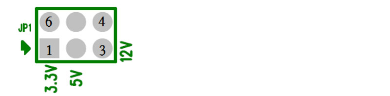
JP1: 5V/3.3V/12V Selector (2.5 mm 2x3 Pin DIP)
| Pin | Description | Note |
| 1-6 | 3.3V | Power supply of +3.3Vdc |
| 2-5 | 5V | Power supply of +5Vdc |
| 3-4 | 12V | Power supply of +12Vdc |
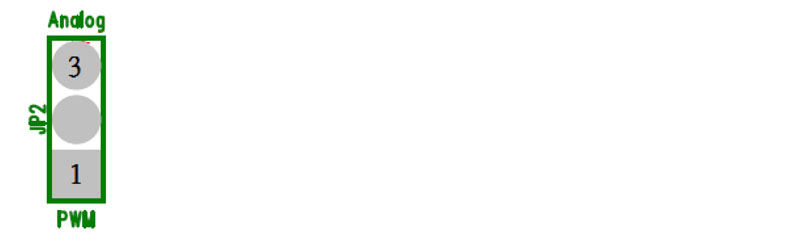
JP2:PWM / Analog selector (2.5 mm 3Pin DIP)
| Pin | Description | Note |
| 1-2 | PWM | Inverter PWM Control |
| 2-3 | Analog | Inverter DC Level Control |
SW1: F/W Timing selector (2.5 mm 2*4Pin SMT)
| Pin | Description | Note |
| 0 | -- | 640*480 |
| 1 | -- | 800*600 |
| 2 | -- | 1024*768 |
| 1,2 | -- | 1280*800 |
| 3 | -- | 1280*1024 |
| 1,3 | -- | 1366*768 |
| 2,3 | -- | 1920*1080 |
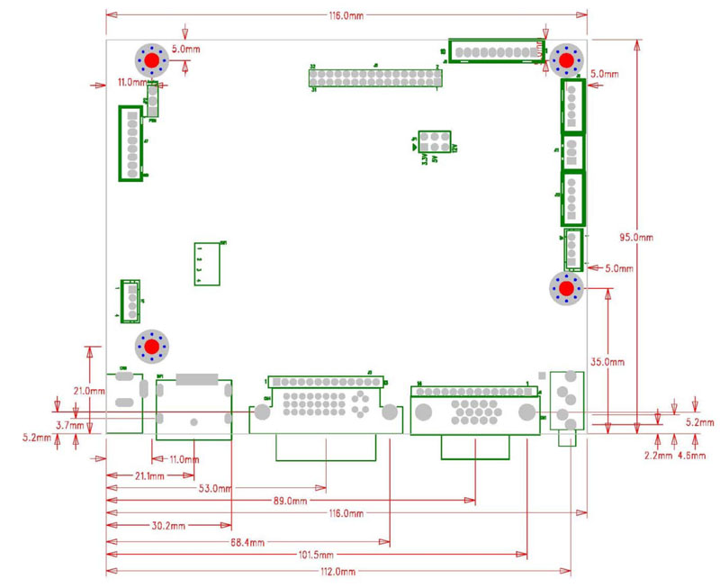
ボードの寸法
ボード寸法 :116mm*95mm
ネジ穴*4:3.5mm
 ダウンロード