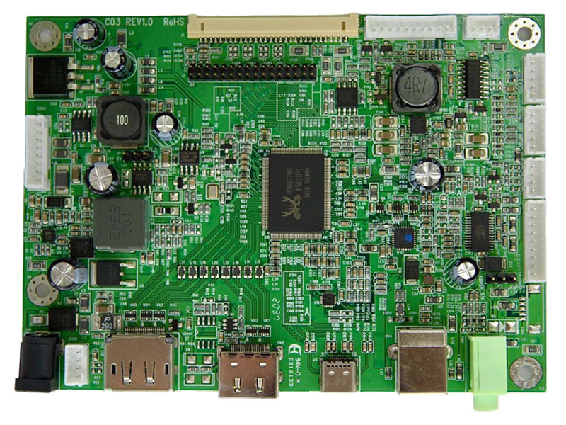
LCDディスプレイモジュール
モデル:C03
このLCD表示モジュールは次のことをサポートします:
◎ 640x480から1920x1200の解像度TFT LCDパネルに対応。
◎ 単一ピクセル(24ビット)またはデュアルピクセル(48ビット)のデジタルRGB出力を供給。
◎ VGA〜1920x1200までの垂直リフレッシュレートを最大75Hz、VESA標準タイミングの高解像度では60Hzをサポート。
◎ デジタル信号入力(DP)をサポート。
◎ 高精細マルチメディアインターフェース(HDMI)入力をサポート。
◎ USBタイプC入力をサポート:DP + USB 2.0。
◎ ステレオオーディオアンプ機能をサポート。2Wx2または10Wx2。
◎ パワーデリバリー(PD)ソースモードをサポート:5V/3Aおよび9V/3A。
◎ USB出力をサポート:USB 2.0 + 抵抗タッチコントロール(オプション)。
◎ RS232サポート(オプション)。
◎ DC 12V入力。
◎ 動作温度:0°Cから+50°C。
◎ 保管温度:-40°Cから+60°C。
◎ RoHS準拠。
問い合わせに追加
◎ 640x480から1920x1200の解像度TFT LCDパネルに対応。
◎ 単一ピクセル(24ビット)またはデュアルピクセル(48ビット)のデジタルRGB出力を供給。
◎ VGA〜1920x1200までの垂直リフレッシュレートを最大75Hz、VESA標準タイミングの高解像度では60Hzをサポート。
◎ デジタル信号入力(DP)をサポート。
◎ 高精細マルチメディアインターフェース(HDMI)入力をサポート。
◎ USBタイプC入力をサポート:DP + USB 2.0。
◎ ステレオオーディオアンプ機能をサポート。2Wx2または10Wx2。
◎ パワーデリバリー(PD)ソースモードをサポート:5V/3Aおよび9V/3A。
◎ USB出力をサポート:USB 2.0 + 抵抗タッチコントロール(オプション)。
◎ RS232サポート(オプション)。
◎ DC 12V入力。
◎ 動作温度:0°Cから+50°C。
◎ 保管温度:-40°Cから+60°C。
◎ RoHS準拠。
仕様
A/D board option
| Mode | Teleview part no. | Description |
| 1 | C03--778APH-- | USB Type B/C+HDMI+DP, audio |
1. Support Timing Table
| Mode | Resolution | V Freq.(Hz) |
| 1 | 640*480 | 60/75 |
| 2 | 720*400 | 70 |
| 3 | 800*600 | 60/75 |
| 4 | 1024*768 | 60/75 |
| 5 | 1280*720 | 60 |
| 6 | 1280*1024 | 60/75 |
| 7 | 1360*768 | 60 |
| 8 | 1440*900 | 60 |
| 9 | 1680*1050 | 60 |
| 10 | 1920*1080 | 60 |
| 11 | 1920*1200 | 60 |
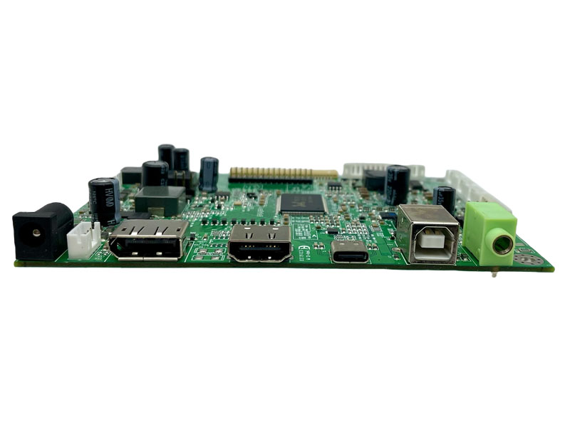
2. Connector Description
● Connector List
| Connector | Function | Note |
| CN1 | Power input connector | ψ2.5 |
| CN2 | HDMI Connector | HDMI A Type |
| CN3 | DP connector | DisplayPort |
| CN4 | USB Input Connector | 4Pin.USB Type B |
| CN5 | Audio Line-in Jack | ψ3.5 |
| CON1 | 12V input Connector | PH 2.0mm. 4Pin.180° |
| CON2 | Backlight driver connector | PH 2.0mm. 8Pin.180° |
| CON3 | UART connector | PH 2.0mm. 5Pin.180° |
| CON4 | USB Output Connector | PH 1.25mm.5Pin.90° |
| CON5 | Resistive touch Connector | PH 2.0mm.5Pin.180° |
| CON6 | IR Connector | PH 2.0mm. 3Pin.180° |
| CON7 | Key board connector | PH 2.0mm.10Pin.180° |
| CON8 | USB Output Connector | PH 2.0mm.9Pin.180° |
| CON9 | Speaker connector | PH 2.0mm. 4Pin.180° |
| J1 | LCD Panel for eDP | 1.25mm. 30Pin.90° |
| J2 | LCD Panel for LVDS | PH 2.0 2*16Pin.90° |
| J3 | USB Connector | 24Pin.USB Type C |
| JP1 | 3.3V/5V selector for panel PH | PH 2.5mm.2x3Pin.180° |
| JP2 | 5V/12V selector for AMP | PH 2.5mm.3Pin.180° |
Pin definition for connector
CN5 : Audio Line-in connector (phone jackψ3.5)

CON1: 12V input Connector (2.0 mm 4Pin DIP)
| Pin | Description | Note |
| 1,4 | +12V | Power supply of +12Vdc |
| 2,3 | GND | Ground |
CON2: Backlight Driver Connector (2.0mm 8 Pin DIP)
| Pin | Function | Note |
| 1,2 | 12V Input | Power supply of +12Vdc |
| 4,6 | GND | Ground |
| 3 | Brightness control | PWM |
| 5 | ON/OFF Control | 5V ON;0V OFF |
| 7,8 | 5V Input/Output | +5Vdc |
Note : 2.0mm 5 pin connector(Pin1~5) is used for standard 12V input
And stand alone backlight driver .
2.0mm 3 pin connector (Pin6~8) is used for 2-in-1 power supply with 5V input .
CON3:UART Connector (2.0 mm 5Pin DIP)
| Pin | Description | Note |
| 1 | 5V | +5Vdc |
| 2 | Key2 | ADC Light Sensor option |
| 3 | Tx | UART RX |
| 4 | Rx | UART RX |
| 5 | GND | Ground |
CON4: USB Output Connector (1.25 mm 5Pin SMD) Option
| Pin | Function | Note |
| 1 | 5V | PC USB 5V |
| 2 | DATA- | USB DATA- |
| 3 | DATA+ | USB DATA+ |
| 4 | GND | Ground |
| 5 | TOUCH | Enable/Disable (Low=Disable) |
CON5: Resistive touch Connector (2.0 mm 5Pin DIP)
| Pin | Function | Note |
| 1 | Y-/UL | -- |
| 2 | SENSE | -- |
| 3 | Y+/UR | -- |
| 4 | X-/LL | -- |
| 5 | X+/LR | -- |
CON6: IR Connector (2.0 mm 3Pin DIP)
| Pin | Function | Note |
| 1 | 5V | +5Vdc |
| 2 | IR | Interrupt input |
| 3 | GND | Ground |
CON7: Key Board Connector (2.0 mm 10Pin DIP)
| Pin | Function | Note |
| 1 | SEL+(RIGHT) | Increase the value |
| 2 | SEL-(LEFT) | Decrease the value |
| 3 | AUTO | Menu Exit |
| 4 | MENU | Enter the main menu |
| 5 | POWER | Power ON/OFF |
| 6 | LED-G | Green LED (Power ON) |
| 7 | LED-R | Red LED (Power saving) |
| 8 | GND | Ground |
| 9 | N.C. | Not connect |
| 10 | N.C. | Not connect |
CON8: USB Output Connector (2.0 mm 9Pin DIP)
| Pin | Function | Note |
| 1 | 5V | +5Vdc |
| 2 | TypeC DATA- | Billboard USB D- |
| 3 | TypeC DATA+ | Billboard USB D+ |
| 4,7 | GND | Ground |
| 5 | PC_USP_SSRX- | USB3 Differential Signal input |
| 6 | PC_USP_SSRX+ | USB3 Differential Signal input |
| 8 | PC_USP_SSTX- | USB3 Differential Signal output |
| 9 | PC_USP_SSTX+ | USB3 Differential Signal output |
CON9: Speaker Connector (2.0 mm 4Pin DIP)
| Pin | Function | Note |
| 1 | R- | Audio Right- |
| 2 | R+ | Audio Right+ |
| 3 | L- | Audio Left- |
| 4 | L+ | Audio Left+ |
J1: Panel connector eDP(1.25 mm 30 Pin SMD) Option
| Pin | Name | Note |
| 1,2 | NC | No contact |
| 3 | GND | Ground |
| 4 | TXAUXN R | Complement signal Auxiliary Channel |
| 5 | TXAUXP R | True signal Auxiliary Channel |
| 6 | GND | Ground |
| 7 | TX0N R | Complement signal link lane0 |
| 8 | TX0P R | True signal link lane0 |
| 9 | GND | Ground |
| 10 | TX1N R | Complement signal link lane1 |
| 11 | TX1P R | True signal link lane1 |
| 12 | GND | Ground |
| 13 | TX2N R | Complement signal link lane2 |
| 14 | TX2P R | True signal link lane2 |
| 15 | GND | Ground |
| 16 | TX3N R | Complement signal link lane3 |
| 17 | TX3P R | True signal link lane3 |
| 18 | GND | Ground |
| 19,20 | 3.3V or 5V or 12V | 3.3V/5V/12V Power supply for panel |
| 21 | DP_HPD | HPD Signal in |
| 22 | BKLT_EN | Backlight enable |
| 23 | BKLT_ADJ | Backlight Adjustment |
| 24,25 | GND | Ground |
| 26,27,28,29 | 12V | +12V Power supply |
| 30 | NC | No contact |
J2:Panel Connector LVDS (2.0 mm 32 Pin DIP)
| Pin | Name ( 8 bit ) | |
| 1,2,3,4 | VDD | Power supply for panel |
| 5,6 | GND | Ground |
| 7 | RXEIN3- | EvenTx3- Data Pin |
| 8 | RXEIN3+ | EvenTx3+ Data Pin |
| 9 | RXEINC- | EvenTx- Clock Pin |
| 10 | RXEINC+ | EvenTx+ Clock Pin |
| 11 | RXEIN2- | EvenTx2- Data Pin |
| 12 | RXEIN2+ | EvenTx2+ Data Pin |
| 13 | RXEIN1- | EvenTx1- Data Pin |
| 14 | RXEIN1+ | EvenTx1+ Data Pin |
| 15 | RXEIN0- | EvenTx0- Data Pin |
| 16 | RXEIN0+ | EvenTx0+ Data Pin |
| 17 | RXOIN3- | OddTx3- Data Pin |
| 18 | RXOIN3+ | OddTx3+ Data Pin |
| 19 | RXOINC- | OddTx- Clock Pin |
| 20 | RXOINC+ | OddTx+ Clock Pin |
| 21 | RXOIN2- | OddTx2- Data Pin |
| 22 | RXOIN2+ | OddTx2+ Data Pin |
| 23 | RXOIN1- | OddTx1- Data Pin |
| 24 | RXOIN1+ | OddTx1+ Data Pin |
| 25 | RXOIN0- | OddTx0- Data Pin |
| 26 | RXOIN0+ | OddTx0+ Data Pin |
| 27,28,29,30 | N.C. | Not connect |
| 31,32 | GND | Ground |
J3: USB Input Connector (24Pin USB Type C SMD)
| Pin | Functio | Note |
| A1 | GND | Ground |
| A2 | TypeC_TX1+ | SuperSpeed differential#1 TX + |
| A3 | TypeC_TX1- | SuperSpeed differential#1 TX - |
| A4 | TypeC_VBUS | VBUS |
| A5 | TypeC_CC1_1 | Configuration channel |
| A6 | TypeC_D+ | USB 2.0 differential position + |
| A7 | TypeC_D- | USB 2.0 differential position - |
| A8 | TypeC_SBU1_1 | Sideband use (SBU) |
| A9 | TypeC_VBUS | VBUS |
| A10 | TypeC_RX2- | SuperSpeed differential#2 RX - |
| A11 | TypeC_RX2+ | SuperSpeed differential#2 RX + |
| A12 | GND | Ground |
| B1 | GND | Ground |
| B2 | TypeC_TX2+ | SuperSpeed differential#2 TX + |
| B3 | TypeC_TX2- | SuperSpeed differential#2 TX - |
| B4 | TypeC_VBUS | VBUS |
| B5 | TypeC_CC2_1 | Configuration channel |
| B6 | TypeC_D+ | USB 2.0 differential position + |
| B7 | TypeC_D- | USB 2.0 differential position - |
| B8 | TypeC_SBU2_1 | Sideband use (SBU) |
| B9 | TypeC_VBUS | VBUS |
| B10 | TypeC_RX1- | SuperSpeed differential#1 RX - |
| B11 | TypeC_RX1+ | SuperSpeed differential#1 RX + |
| B12 | GND | Ground |
JP1/LE1: Panel B+ 3.3V / 5V / 12V selector (2.5 mm 3Pin DIP)
| Pin | Description | Note |
| 1-2 | 5V | Power supply of +5dc |
| 2-3 | 3.3V | Power supply of +3.3Vdc |
| LE1 | 12 | Power supply of +12Vdc |
JP2: Audio power selector (2.5 mm 3Pin DIP)
| Pin | Description | Note |
| 1-2 | 5V input | 2W x 2 output |
| 2-3 | 12V input | 10W x 2 output |
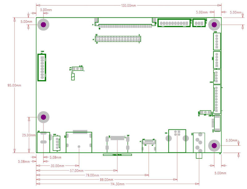
ボードの寸法
ボード寸法 :130mm*95mm
スクリューホール*4:3.5mm